Vacuum line missing

Pretzel9872

New member
Joined
Dec 21, 2024
Messages
4
Reaction score
1
Points
3
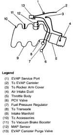
I replaced the fuel pressure regulator in my 2004 Grand Am 3.4L and noticed the old one had a bit of tube on top. The tube had broken off at some point, and now I'm confused about where to connect it. I got some tubes for it, and I found a diagram for the right engine (below) showing how the vacuum lines are supposed to go. According to the diagram, I need to connect the fuel pressure regulator (7) to the MAP sensor (12). the problem is that the MAP sensor is connected via a larger tube to a nipple at point 8 (diagram says "To Transaxle," which I don't understand).
I've seen other engines like this in the videos, and both 7 and 8 had tubes going towards 12. What should I do?
I'll take pictures of my engine tomorrow when it's light out.
1734833413531.webp
image source: Vaccuum Diagram: Needing a Vacuum Diagram; Where Can I Find One?
 
I replaced the fuel pressure regulator in my 2004 Grand Am 3.4L and noticed the old one had a bit of tube on top. The tube had broken off at some point, and now I'm confused about where to connect it. I got some tubes for it, and I found a diagram for the right engine (below) showing how the vacuum lines are supposed to go. According to the diagram, I need to connect the fuel pressure regulator (7) to the MAP sensor (12). the problem is that the MAP sensor is connected via a larger tube to a nipple at point 8 (diagram says "To Transaxle," which I don't understand).
I've seen other engines like this in the videos, and both 7 and 8 had tubes going towards 12. What should I do?
I'll take pictures of my engine tomorrow when it's light out.
View attachment 7406
image source: Vaccuum Diagram: Needing a Vacuum Diagram; Where Can I Find One?
The tube you refer to on the pressure regulator, is that the only vacuum connection?
What year and which engine?
 
The tube you refer to on the pressure regulator, is that the only vacuum connection?
What year and which engine?
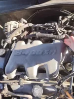
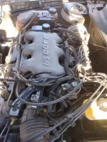
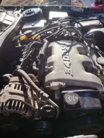
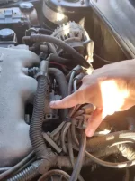
Here's some pictures of the engine:
1734897162489.webp1734897176050.webp
1734897188062.webp
Here are points 7 and 8 from the diagram. The right one is the fuel pressure regulator (7), and the left is 8:
1734897247668.webp
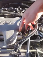
Here's the MAP sensor (index finger). Thumb is pointing to the tube that is currently linking the MAP sensor to point 8:
1734897311365.webp

I put a bit of tube on the fuel pressure regulator b/c that's how I remember it being (though I could be wrong). It runs, and my uncle says it sounds fine, but I think it sounds like it's struggling.
 
Just to get names clear, tubes are metal, vacuum hose is rubber.
Is the vacuum hose connected to the regulator connected on both ends.
The regulator and the map sensor share a common vacuum source appearing to come from valve cover using a T connection.
______________________________
 
The hose connected to the regulator isn't currently connected to anything else.
I've seen a few other pictures of this type of engine, and I think I need to run hose between the regulator and the MAP sensor and then block off the other port. I found the official diagram: 1734915684332.webpThis forum suggests that that extra port is for the HVAC system, but I haven't found any other information about that.
 
Not sure what other port you are referring to but it definitely shows the regulator connected to the map.
 
Update: I did some more research and figured it out. I ran vacuum hose to connect the fuel pressure regulator and the MAP sensor.
The confusion came from a nipple/port on the engine near the regulator. Someone had connected that port to the map instead of the regulator. That port is for HVAC controls. It's supposed to connect to a hard white vacuum hose, but mine had broken off at some point. My uncle had told me that the HVAC controls weren't working (vents blew only from the face and wouldn't change to feet or defrost). When I connected that port to the white vacuum hose, the HVAC controls started working.
So two problems solved at once :giggle:(y)
 
Back
Top